UE5 – SliceProceduralMesh 함수 분석

UProceduralMeshComponent의 메쉬를 평면 기준으로 자르는 함수이다.
Plane 준비
우선 컴포넌트 로컬 공간 기준으로 평면을 준비한다. 평면을 정의하기 위한 평면상의 한 점과 평면의 노말벡터를 인자로 받는다.
FTransform ProcCompToWorld = InProcMesh->GetComponentToWorld();

FVector LocalPlanePos    = ProcCompToWorld.InverseTransformPosition     ( PlanePosition );
FVector LocalPlaneNormal = ProcCompToWorld.InverseTransformVectorNoScale( PlaneNormal   );

LocalPlaneNormal = LocalPlaneNormal.GetSafeNormal();

FPlane SlicePlane(LocalPlanePos, LocalPlaneNormal);
그리고 이 점의 위치와 노말을 로컬 공간으로 변환 후, 평면을 생성한다.
임시 데이터 컨테이너들 선언
메쉬를 자르면서 발생하는 데이터를 캐슁하기 위한 임시 데이터 컨테이너들을 선언한다.
// 메쉬를 자를때 분리되며 생기는 메쉬 섹션을 담아두는 곳
TArray< FProcMeshSection > OtherSections;

// 메쉬를 자를때 분리되며 생기는 메쉬의 머티리얼을 담아두는 곳
TArray< UMaterialInterface* > OtherMaterials;

// 폴리곤이 잘리면서 발생하는 엣지를 담아두는 곳
TArray< FUtilEdge3D > ClipEdges;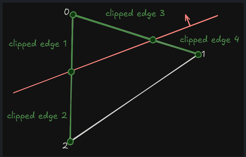
FUtilEdge3D
엣지는 2개의 정점으로 표현할 수 있다. 이 구조체는 2개의 정점을 가지고 엣지를 표현하는 구조체이다.
각 섹션별 메쉬마다 처리
메쉬의 바운더리를 평면이 관통하는지 검사
for ( int32 SectionIndex = 0; SectionIndex < InProcMesh->GetNumSections(); SectionIndex++ )
{
    FProcMeshSection* BaseSection = InProcMesh->GetProcMeshSection( SectionIndex );

    if ( BaseSection != nullptr && BaseSection->ProcIndexBuffer.Num() > 0 && BaseSection->ProcVertexBuffer.Num() > 0 )
    {
        int32 BoxCompare = BoxPlaneCompare( BaseSection->SectionLocalBox, SlicePlane );

        if ( BoxCompare == -1 )
        {
            // 이 섹션의 메쉬는 모든 영역이 평면으로 잘리는 영역이다.
            // 섹션 그대로 OtherSection으로 지정한다.
            if ( bCreateOtherHalf )
            {
               OtherSections.Add( *BaseSection );
               OtherMaterials.Add( InProcMesh->GetMaterial( SectionIndex ) );
            }

            // 이 컴포넌트에서는 완전히 잘려 나가는 영역이므로 제거한다.
            InProcMesh->ClearMeshSection( SectionIndex );
        }
        else if ( BoxCompare == 1)
        {
            // 이 섹션은 잘리지 않는 영역에 완전히 포함되므로 유지한다.
        }
        else
        {
            // 영역의 일부가 평면에 의해 잘린다. 여기서부터가 가장 중요하다.
        }
    }
}
박스와 평면이 관통하는지 어떻게 검사할까? 코드에서는 박스의 중심점과 평면과의 거리를 구한다.
int32 BoxPlaneCompare( FBox InBox, const FPlane& InPlane )
{
    FVector BoxCenter, BoxExtents;
    InBox.GetCenterAndExtents( BoxCenter, BoxExtents );

    // 박스의 중심점과 평면과의 거리를 구한다.
    FVector::FReal BoxCenterDist = InPlane.PlaneDot( BoxCenter );

    // See size of box in plane normal direction
    FVector::FReal BoxSize = FVector::BoxPushOut( InPlane, BoxExtents );

    if ( BoxCenterDist > BoxSize )
    {
       return 1;
    }
    else if ( BoxCenterDist < -BoxSize )
    {
       return -1;
    }
    else
    {
       return 0;
    }
}
메쉬의 바운더리를 평면이 관통할 때 슬라이스 처리
BoxPlaneCompare의 결과값이 0인, 즉 일부가 평면에 걸쳐지는 경우 메쉬가 슬라이스 된다고 했다.
이 슬라이스 시키는 코드를 보자.
잘려나갈 메쉬를 구성하기 위한 사전 준비
FProcMeshSection NewSection;

FProcMeshSection* NewOtherSection = nullptr;
if ( bCreateOtherHalf )
{
    int32 OtherSectionIndex = OtherSections.Add( FProcMeshSection() );
    NewOtherSection = &OtherSections[ OtherSectionIndex ];

    OtherMaterials.Add( InProcMesh->GetMaterial( SectionIndex ) );
}
일단 잘린 메쉬로 갱신하기 위해 갱신될 메쉬의 데이터가 담길 NewSection을 선언한다.
그리고 잘려나간 메쉬를 다른 컴포넌트로 지정하여 보관하기 위해 NewOtherSection과 머티리얼을 동일하게 설정해주기 위해 OtherMaterials에 현재 섹션의 머티리얼을 캐슁해둔다. 잘려나간 메쉬를 보관하지 않는다면 ( !bCreateOtherHalf ) 이 부분은 무시된다.
잘린 후 잔존하는 메쉬와 잘려나갈 메쉬의 정점 인덱스 분류
TMap< int32, int32 > BaseToSlicedVertIndex;
TMap< int32, int32 > BaseToOtherSlicedVertIndex;

const int32 NumBaseVerts = BaseSection->ProcVertexBuffer.Num();

TArray< float > VertDistance;
VertDistance.AddUninitialized( NumBaseVerts );

{
    FProcMeshVertex& BaseVert = BaseSection->ProcVertexBuffer[ BaseVertIndex ];
    VertDistance[ BaseVertIndex ] = SlicePlane.PlaneDot( BaseVert.Position );

    if (VertDistance[ BaseVertIndex ] > 0.f)
    {
       int32 SlicedVertIndex = NewSection.ProcVertexBuffer.Add( BaseVert );
       NewSection.SectionLocalBox += BaseVert.Position;
       BaseToSlicedVertIndex.Add( BaseVertIndex, SlicedVertIndex );
    }
    else if( NewOtherSection != nullptr )
    {
       int32 SlicedVertIndex = NewOtherSection->ProcVertexBuffer.Add( BaseVert );
       NewOtherSection->SectionLocalBox += BaseVert.Position;
       BaseToOtherSlicedVertIndex.Add( BaseVertIndex, SlicedVertIndex );
    }
}
이 섹션의 정점들을 슬라이스할 평면 기준으로 거리를 측정하여 계속 포함될 정점 인덱스( BaseToSlicedVertIndex )와 다른 섹션으로 이동할 정점 인덱스( BaseToOtherSlicedVertIndex )로 분류한다. 정점이 평면의 노말 방향쪽에 있으면 BaseToSliceVertIndex, 그 반대 방향쪽에 있으면 BaseToOtherSlicedVertIndex로 분류한다.
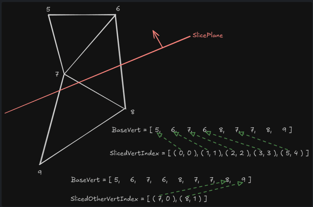
간단히 분류되는 정점 인덱스들을 도식화하면 위와 같게 된다.NewSection.SectionLocalBox += BaseVert.Position; 이 코드는 FBox에서 FVector가 추가되면 이 위치를 포함하는 새로운 영역이 계산된다.
폴리곤 단위에서의 처리
for ( int32 BaseIndex = 0; BaseIndex < BaseSection->ProcIndexBuffer.Num(); BaseIndex += 3 )
{
    int32 BaseV[ 3 ];
    int32* SlicedV[ 3 ];
    int32* SlicedOtherV[ 3 ];

    for ( int32 i = 0; i < 3; i++)
    {
        BaseV[ i ] = BaseSection->ProcIndexBuffer[ BaseIndex + i ];

        SlicedV[ i ] = BaseToSlicedVertIndex.Find( BaseV[ i ] );

        if ( bCreateOtherHalf )
        {
            SlicedOtherV[ i ] = BaseToOtherSlicedVertIndex.Find( BaseV[ i ] );

            check( ( SlicedV[ i ] != nullptr ) != ( SlicedOtherV[ i ] != nullptr ) );
        }
    }
폴리곤 단위로처리를 하는 반복문이므로 이번에 처리할 정점 인덱스들을 준비한다. 각각 기본( BaseV ), 잔존할 메쉬( SlicedV ), 잘려나갈 메쉬( SlicedOtherV의 정점 인덱스이다. 잘린 후 잔존하는 메쉬와 잘려나갈 메쉬의 정점 인덱스 분류에서 분류된 인덱스 맵을 가지고 정점버퍼의 인덱스를 찾는 형식이다.
도식화된 그림 기준으로 첫 루프에서 각각 채워지는 정점 인덱스는 다음과 같게 된다.
BaseV        = [ 0, 1, 2 ];
SlicedV      = [ &BaseToSlicedVertIndex[ 0 ], &BaseToSlicedVertIndex[ 1 ], &BaseToSlicedVertIndex[ 2 ] ]; // [ &0, &1, &2 ]
SlicedOtherV = [ nullptr, nullptr, nullptr ];
check( ( SlicedV[ i ] != nullptr ) != ( SlicedOtherV[ i ] != nullptr ) );는 잘려나가는 메쉬를 보존할 때 잔존 메쉬 혹은 잘려나가는 메쉬 둘중 하나의 정점 인덱스가 존재하지 않으면, 즉 이도 저도 아닌 정점이 존재한다면 오류로 판단하는 것이다.
폴리곤이 구성되지 않을때 처리
잔존 메쉬에서 폴리곤을 온전히 구성할 수 있는 정점들이 모두 존재하는 경우 갱신할 섹션에 그대로 인덱스들을 추가해준다.
if ( SlicedV[ 0 ] != nullptr && SlicedV[ 1 ] != nullptr && SlicedV[ 2 ] != nullptr )
{
    NewSection.ProcIndexBuffer.Add( *SlicedV[ 0 ] );
    NewSection.ProcIndexBuffer.Add( *SlicedV[ 1 ] );
    NewSection.ProcIndexBuffer.Add( *SlicedV[ 2 ] );
}
정점 인덱스가 하나도 존재하지 않는 경우에 새로운 컴포넌트를 생성하는 경우 해당 섹션에 인덱스들을 추가해준다.
else if ( SlicedV[ 0 ] == nullptr && SlicedV[ 1 ] == nullptr && SlicedV[ 2 ] == nullptr )
{
    if ( NewOtherSection != nullptr )
    {
        NewOtherSection->ProcIndexBuffer.Add( *SlicedOtherV[ 0 ] );
        NewOtherSection->ProcIndexBuffer.Add( *SlicedOtherV[ 1 ] );
        NewOtherSection->ProcIndexBuffer.Add( *SlicedOtherV[ 2 ] );
    }
}
평면에 의해서 잘리는 폴리곤의 처리
정점이 한개, 혹은 두개만 있는 경우 그러니까 폴리곤을 온전하게 구성하지 못하는 정점만 있는 구간은 평면으로 잘리는 폴리곤이다.
이 폴리곤은 평면에 의해서 분리되기 때문에 잔존 메쉬쪽에 0정점 하나만의 정보를 가지게 되고 다른쪽에는 1, 2정점 두개의 정보만 가지게 된다.
BaseV        = [ 0, 1, 2 ];
SlicedV      = [ &0, nullptr, nullptr ];
SlicedOtherV = [ nullptr, &1, &2 ];
위와 같은 데이터를 처리하게 되는 것이다.
이런 불안전한 부분은 완전하게 폴리곤 구성이 될 수 있도록 정점 및 폴리곤을 추가해준다.
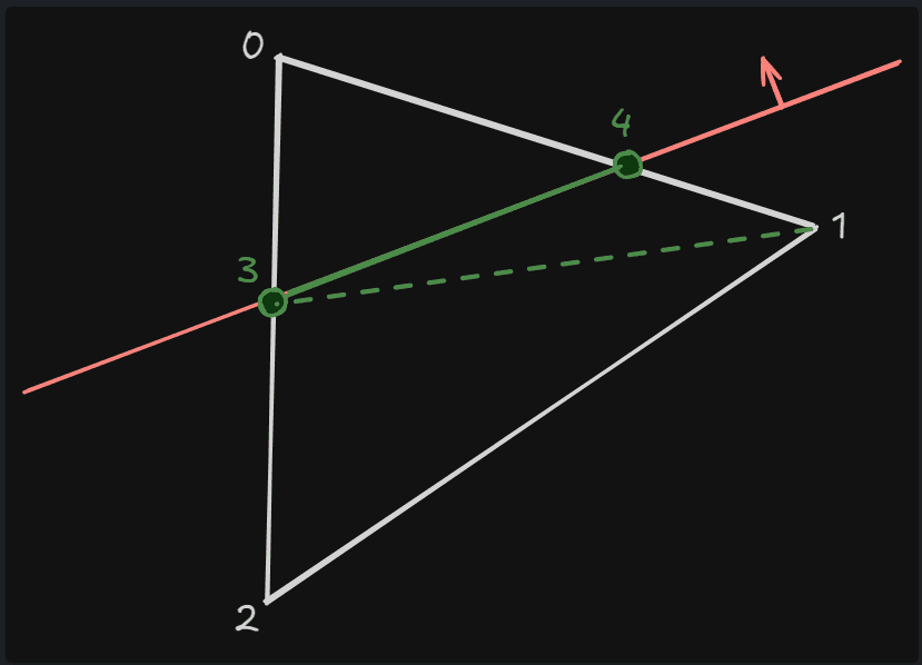
3, 4 정점이 추가된 후 각각 [ 0, 3, 4 ], [ 3, 1, 4 ], [ 4, 1, 2] 이렇게 3개의 폴리곤으로 확장될 수 있다.
int32 FinalVerts[ 4 ];
int32 NumFinalVerts = 0;

int32 OtherFinalVerts[ 4 ];
int32 NumOtherFinalVerts = 0;

FUtilEdge3D NewClipEdge;
int32 ClippedEdges = 0;

float PlaneDist[ 3 ];
PlaneDist[ 0 ] = VertDistance[ BaseV[ 0 ] ];
PlaneDist[ 1 ] = VertDistance[ BaseV[ 1 ] ];
PlaneDist[ 2 ] = VertDistance[ BaseV[ 2 ] ];
위 그림과 같이 새로 구성되는 정점은 최대 4개까지 될 수 있기 때문에 FinalVerts, OtherFinalVerts는 각각 4크기로 준비를 해둔다.
그리고 폴리곤 기준에서 각 정점들의 평면과의 거리를 다시 가져온다.
엣지별 처리
폴리곤은 3개의 엣지를 가지므로 이 엣지별로 처리를 한다.
for ( int32 EdgeIdx = 0; EdgeIdx < 3; EdgeIdx++ )
{
    int32 ThisVert = EdgeIdx;

    if ( SlicedV[ ThisVert ] != nullptr )
    {
        check( NumFinalVerts < 4 );
        FinalVerts[ NumFinalVerts++ ] = *SlicedV[ ThisVert ];
    }
    else if( bCreateOtherHalf )
    {
        check( NumOtherFinalVerts < 4 );
        OtherFinalVerts[ NumOtherFinalVerts++ ] = *SlicedOtherV[ ThisVert ];
    }
우선 기존에 존재하는 정점을 잔존 or 잘려나가는 2개로 분류한다. 도식화 기준으로 첫 루프에서는 0이 FinalVerts에 들어가게 된다.
    int32 NextVert = (EdgeIdx + 1) % 3;

    if ( ( SlicedV[ EdgeIdx ] == nullptr ) != ( SlicedV[ NextVert ] == nullptr ) )
    {
        float Alpha = -PlaneDist[ ThisVert ] / ( PlaneDist[ NextVert ] - PlaneDist[ ThisVert ] );

        FProcMeshVertex InterpVert = InterpolateVert( BaseSection->ProcVertexBuffer[ BaseV[ ThisVert ] ], BaseSection->ProcVertexBuffer[ BaseV[ NextVert ] ], FMath::Clamp( Alpha, 0.0f, 1.0f ) );

        int32 InterpVertIndex = NewSection.ProcVertexBuffer.Add( InterpVert );

        NewSection.SectionLocalBox += InterpVert.Position;

        check( NumFinalVerts < 4 );
        FinalVerts[ NumFinalVerts++ ] = InterpVertIndex;

        if ( NewOtherSection != nullptr )
        {
            int32 OtherInterpVertIndex = NewOtherSection->ProcVertexBuffer.Add( InterpVert );
            NewOtherSection->SectionLocalBox += InterpVert.Position;
            check( NumOtherFinalVerts < 4 );
            OtherFinalVerts[ NumOtherFinalVerts++ ] = OtherInterpVertIndex;
        }

        check( ClippedEdges < 2 );
        if ( ClippedEdges == 0 )
        {
            NewClipEdge.V0 = (FVector3f)InterpVert.Position;
        }
        else
        {
            NewClipEdge.V1 = (FVector3f)InterpVert.Position;
        }

        ClippedEdges++;
    }
}
현재 엣지를 구성하는 두 정점 중 하나라도 없는 경우 새로운 정점을 생성한다.
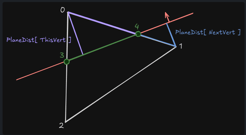
새로운 정점의 위치는 현재 정점( 0 )과 다음 정점( 1 ) 각각의 평면과의 거리를 이용해 계산된 비율값으로 보간하여 새로운 정점( 3 )의 위치가 결정된다. 이렇게 새롭게 생성된 정점은 갱신될 메쉬 섹션에 바로 추가되고, 바운더리 계산에도 포함된다.
int32 InterpVertIndex = NewSection.ProcVertexBuffer.Add( InterpVert );
NewSection.SectionLocalBox += InterpVert.Position;
새롭게 생성된 정점에 의해 만들어지는 Face의 인덱스와 엣지는 FinalVerts, OtherFinalVerts ClipEdges에 보관되며 섹션의 인덱스 버퍼 내용 또한 갱신한다.
for ( int32 VertexIndex = 2; VertexIndex < NumFinalVerts; VertexIndex++ )
{
    NewSection.ProcIndexBuffer.Add( FinalVerts[ 0 ] );
    NewSection.ProcIndexBuffer.Add( FinalVerts[ VertexIndex - 1 ] );
    NewSection.ProcIndexBuffer.Add( FinalVerts[ VertexIndex ] );
}

if ( NewOtherSection != nullptr )
{
    for ( int32 VertexIndex = 2; VertexIndex < NumOtherFinalVerts; VertexIndex++ )
    {
        NewOtherSection->ProcIndexBuffer.Add( OtherFinalVerts[ 0 ] );
        NewOtherSection->ProcIndexBuffer.Add( OtherFinalVerts[ VertexIndex - 1 ] );
        NewOtherSection->ProcIndexBuffer.Add( OtherFinalVerts[ VertexIndex ] );
    }
}

check( ClippedEdges != 1 );

if ( ClippedEdges == 2 )
{
    ClipEdges.Add( NewClipEdge );
}NewOtherSection의 경우 NumOtherFinalVerts가 4개가 된다. [ 1, 2, 3, 4 ]따라서 2개의 Face가 새롭게 생성된다.
이후 Face는 다음과 같이 갱신된다.
잘린 단면의 머티리얼 처리
위와 같이 메쉬를 구성하는 폴리곤이 평면에 의해 잘리고 새롭게 구성되었을 때 잘린 단면에 대해서는 폴리곤이 존재하지 않는다. 이 단면에 대해 따로 머티리얼을 설정하지 않으면 뚫린 모습을 보여주기에 별도의 처리를 할 필요가 없다. 하지만 머티리얼 설정을 하는 경우에는 이 단면에 대해서 폴리곤을 생성해주어야 한다.
단면에 대한 섹션의 결정
if ( CapOption != EProcMeshSliceCapOption::NoCap && ClipEdges.Num() > 0 )
{
    FProcMeshSection CapSection;
    int32 CapSectionIndex = INDEX_NONE;


    if ( CapOption == EProcMeshSliceCapOption::UseLastSectionForCap )
    {
        CapSectionIndex = InProcMesh->GetNumSections() - 1;
        CapSection = *InProcMesh->GetProcMeshSection( CapSectionIndex );
    }
    else
    {
        CapSectionIndex = InProcMesh->GetNumSections();
    }
머티리얼 설정이 필요한 경우 마지막 섹션의 머티리얼을 사용할지, 새로운 머티리얼을 사용할지에 따라 기존 섹션을 참조하거나 새로운 섹션을 생성할 준비를 한다.
단면에 대한 폴리곤 생성 준비
TArray< FUtilEdge2D > Edges2D;
FUtilPoly2DSet PolySet;
FGeomTools::ProjectEdges( Edges2D, PolySet.PolyToWorld, ClipEdges, SlicePlane );

FGeomTools::Buid2DPolysFromEdges( PolySet.Polys, Edges2D, FColor( 255, 255, 255, 255 ) );

int32 CapVertBase = CapSection.ProcVertexBuffer.Num();
int32 CapIndexBase = CapSection.ProcIndexBuffer.Num();
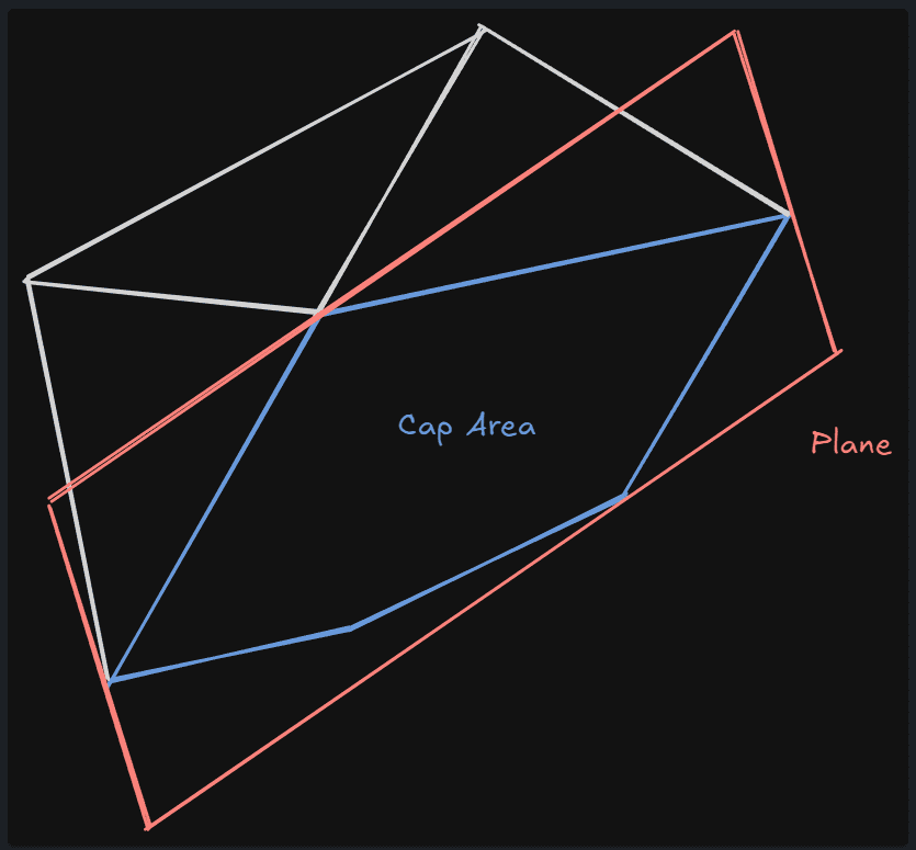
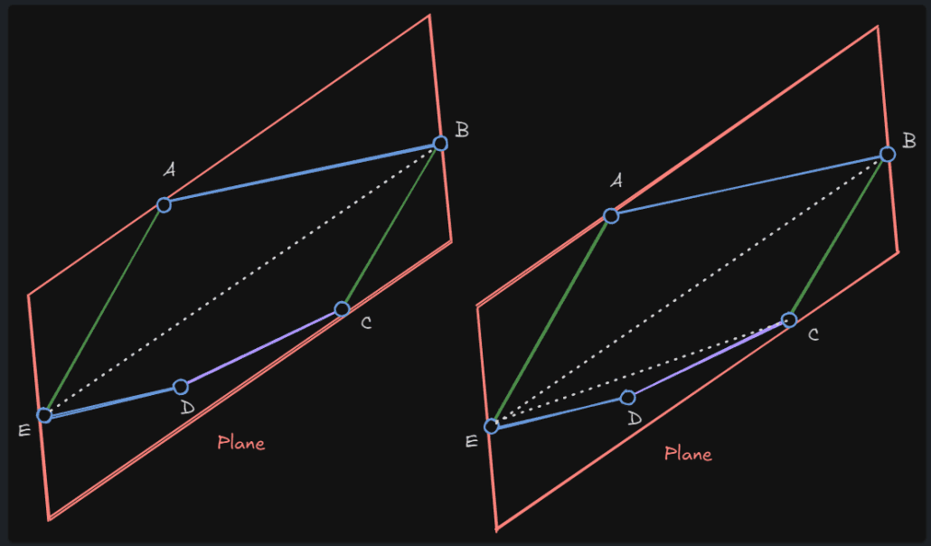
평면에 의해 새로 생성된 엣지의 변환
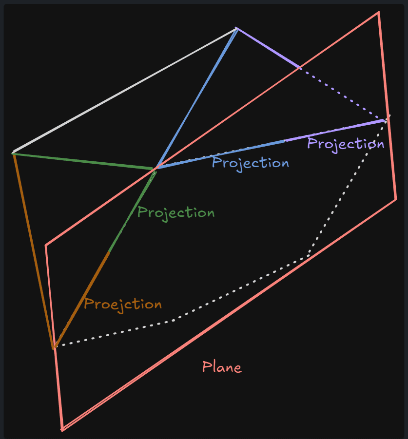
새롭게 생성된 엣지를 메쉬를 자르는 평면 공간으로 변환한다. PolySet.PolyToWorld는 변환된 엣지를 다시 월드 공간 기준으로 변환하는데 사용된다. 위 그림에서 녹색 엣지들이 평면 공간으로 변환될 엣지들이고 이렇게 변환된 엣지는 Edges2D에 보관된다.
평면 자체가 2차원이므로 평면 공간으로 변환된다는 것은 곧 평면의 2D공간으로 곧 투영된다는 것이다.
void FGeomTools::ProjectEdges( TArray< FUtilEdge2D >& Out2DEdges, FMatrix& ToWorld, const TArray< FUtilEdge3D >& In3DEdges, const FPlane& InPlane )
{
    FVector BasisX, BasisY, BasisZ;
    BasisZ = InPlane;
    BasisZ.FindBestAxisVectors( BasisX, BasisY );
    ToWorld = FMatrix( BasisX, BasisY, InPlane, BasisZ * InPlane.W );

    Out2DEdges.AddUninitialized( In3DEdges.Num() );

    for ( int32 i = 0; i < In3DEdges.Num(); i++ )
    {
        FVector P = ToWorld.InverseTransformPosition( FVector( In3DEdges[ i ].V0 ) );
        Out2DEdges[ i ].V0.X = P.X;
        Out2DEdges[ i ].V0.Y = P.Y;

        P = ToWorld.InverseTransformPosition( FVector( In3DEdges[ i ].V1 ) );
        Out2DEdges[ i ].V1.X = P.X;
        Out2DEdges[ i ].V1.Y = P.Y;
    }
}
코드를 보면 주어진 평면에 대한 월드 공간 기준의 매트릭스( ToWorld )를 먼저 생성한다음 InverseTransformPosition을 이용해 평면 공간으로 변환한다.
평면 공간으로 변환된 엣지를 가지고 폴리곤 생성
void FGeomTools::Buid2DPolysFromEdges( TArray< FUtilPoly2D >& OutPolys, const TArray< FUtilEdge2D >& InEdges, const FColor& VertColor )
{
    TArray< FUtilEdge2D > EdgeSet = InEdges;

    while ( EdgeSet.Num() > 0 )
    {
        FUtilPoly2D NewPoly;
        FUtilEdge2D FirstEdge = EdgeSet.Pop();

        NewPoly.Verts.Add( FUtilVertex2D( FirstEdge.V0, VertColor ) );
        NewPoly.Verts.Add( FUtilVertex2D( FirstEdge.V1, VertColor ) );

        FVector2D PolyEnd = NewPoly.Verts[ NewPoly.Verts.Num() - 1 ].Pos;
        FUtilEdge2D NextEdge;

        while ( FindNextEdge( NextEdge, PolyEnd, EdgeSet ) )
        {
            NewPoly.Verts.Add( FUtilVertex2D( NextEdge.V1, VertColor ) );
            PolyEnd = NewPoly.Verts[ NewPoly.Verts.Num() - 1 ].Pos;
        }

        float CloseDistSqr = ( NewPoly.Verts[ 0 ].Pos - NewPoly.Verts[ NewPoly.Verts.Num() - 1 ].Pos ).SizeSquared();

        if ( NewPoly.Verts.Num() >= 4 && CloseDistSqr < FMath::Square( EdgeMatchTolerance ) )
        {
            NewPoly.Verts.RemoveAt( NewPoly.Verts.Num() - 1 );

            FixPolyWinding( NewPoly );

            OutPolys.Add( NewPoly );
        }
    }
}
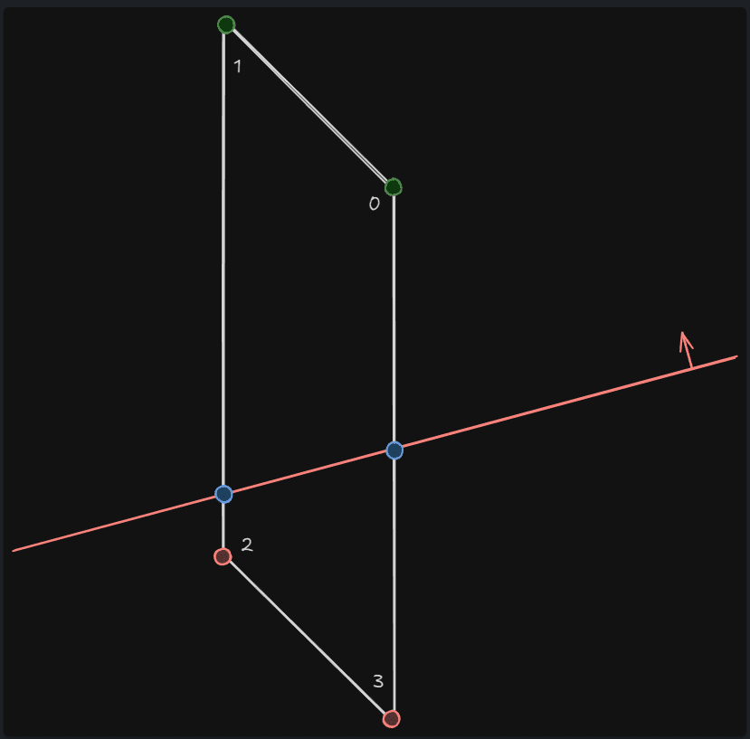
엣지들을 형성하는 정점들을 연속성이 있게 정렬
가장 먼저 우선적으로 하는것은 엣지들을 형성하고 있는 정점을 연속성 있게 정렬하는 것이다. 아래 그림을 보면 엣지들이 순서가 불규칙하게 리스트에 담겨있을 수 있다. 폴리곤들을 생성하기전에 오른쪽 그림처럼 정점들을 순서대로 정렬해야 한다.
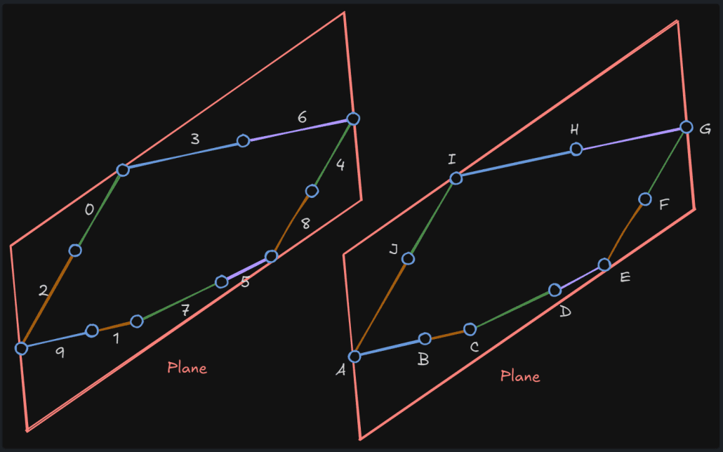
평면에 투영된 엣지가 총 10개가 있다고 가정할 때 가장 마지막 엣지를 Pop한다. ( 9번째 엣지 ) 그리고 남은 엣지를 순회하며 근접한 다음 엣지를 찾는다. 9번 엣지 기준으로는 1번 엣지가 다음 엣지가 될 수 있다. 이렇게 근접한 엣지를 찾는 함수가 바로 FindNextEdge이다.
static bool FindNextEdge( FUtilEdge2D& OutNextEdge, const FVector2D& Start, TArray< FUtilEdge2D >& InEdgeSet )
{
    float ClosestDistSqr = UE_BIG_NUMBER;
    FUtilEdge2D OutEdge;
    int32 OutEdgeIndex = INDEX_NONE;

    for ( int32 i = 0; i < InEdgeSet.Num(); i++ )
    {
        float DistSqr = ( InEdgeSet[ i ].V0 - Start ).SizeSquared();

        if ( DistSqr < ClosestDistSqr )
        {
            ClosestDistSqr = DistSqr;
            OutNextEdge = InEdgeSet[ i ];
            OutEdgeIndex = i;
        }

        DistSqr = ( InEdgeSet[ i ].V1 - Start ).SizeSquared();

        if ( DistSqr < ClosestDistSqr )
        {
            ClosestDistSqr = DistSqr;
            OutNextEdge = InEdgeSet[ i ];
            Swap( OutNextEdge.V0, OutNextEdge.V1 );
            OutEdgeIndex = i;
        }
    }

    if ( ClosetDistSqr < FMath::Square( EdgeMAtchTolerance ) )
    {
        check( OutEdgeIndex != INDEX_NONE );
        InEdgeSet.RemoveAt( OutEdgeIndex );

        return true;
    }

    return false;
}Start는 남은 엣지 리스트 중 마지막 엣지의 2번째 정점이다. 이 정점과 엣지 리스트의 첫번째 엣지부터 순회하며 가장 거리가 가까운 엣지를 찾으며, 이 엣지의 거리가 근접하다고 판단되면 성공적으로 다음 엣지를 찾는것으로 간주하며 이렇게 찾은 다음 엣지는 리스트에서 제거한다. 즉 위 그림 기준으로 9번 엣지의 가장 가까운 1번 엣지를 찾았으므로 1번 엣지는 제거된다.
while ( FindNextEdge( NextEdge, PolyEnd, EdgeSet ) )
{
    NewPoly.Verts.Add( FUtilVertex2D( NextEdge.V1, VertColor ) );
    PolyEnd = NewPoly.Verts[ NewPoly.Verts.Num() - 1 ].Pos;
}
이후엔 1번 엣지의 2번째 정점을 파라메터로 넘겨 동일하게 다음 근접 엣지를 찾는다. 그림 기준으로 7번 엣지가 된다. 이런식으로 연속성을 가질 수 있도록 엣지들의 정점을 정렬해나가는데, 이 정렬된 정점들은 NewPoly.Verts에 차례대로 추가된다. 모든 엣지에 대해 처리가 되면 가장 마지막 정점은 통상적으로 첫번째 엣지의 첫번째 점이 되므로 이것은 제거한다.
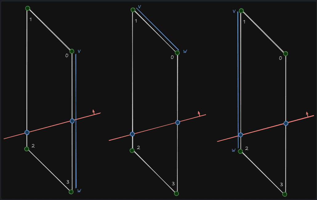
정점을 폴리곤이 형성될 수 있도록 정리
정렬된 정점들을 가지고 한번 더 정리한다.
중복되는 엣지를 형성하는 정점을 제거하고 올바르게 렌더링될 수 있도록 정점들의 순서도 다시 정렬한다.
static void FixPolyWinding( FUtilPoly2D& Poly )
{
float TotalAngle = 0.f;
for ( int32 i = Poly.Verts.Num() - 1; i >= 0; i-- )
{
int32 AIndex = (i == 0) ? Poly.Verts.Num() - 1 : i - 1;
int32 BIndex = i;
int32 CIndex = (i + 1) % Poly.Verts.Num();
float ABDistSqr = ( Poly.Verts[ BIndex ].Pos - Poly.Verts[ AIndex ].Pos ).SizeSquared();
FVector2D ABEdge = ( Poly.Verts[ BIndex ].Pos - Poly.Verts[ AIndex ].Pos ).GetSafeNormal();
float BCDistSqr = ( Poly.Verts[ CIndex ].Pos - Poly.Verts[ BIndex ].Pos ).SizeSquared();
FVector2D BCEdge = ( Poly.Verts[ CIndex ].Pos - Poly.Verts[ BIndex ].Pos ).GetSafeNormal();
if ( ABDistSqr < 0.0001f || BCDistSqr < 0.0001f || ABEdge.Equals( BCEdge, 0.01f ) )
{
Poly.Verts.RemoveAt( i );
}
else
{
TotalAngle += FMath::Asin( ABEdge ^ BCEdge );
}
}
if ( TotalAngle < 0.f )
{
int32 NumVerts = Poly.Verts.Num();
TArray< FUtilVertex2D > NewVerts;
NewVerts.AddUninitialized( NumVerts );
for( int32 i = 0; i < NumVerts; i++ )
{
NewVerts[ i ] = Poly.Verts[ NumVerts - (1 + i) ];
}
Poly.Verts = NewVerts;
}
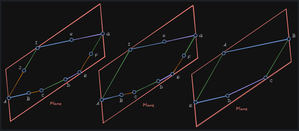
}처음 루프에서 AIndex, BIndex, CIndex는 각각 I, J, A가 된다. 따라서 IJ와 JA엣지의 길이와 방향을 구하게 된다. 그리고 각 엣지의 길이가 0.0001f보다 작거나 두 엣지의 방향이 거의 동일하다면 동일한 엣지로 판단하여 J를 제거한다.
다음 루프에서 AIndex, BIndex, CIndex는 각각 H, I, A가 되며 동일한 루직을 수행한다. 이 경우에 HI, IA두 엣지는 서로 다른 엣지이므로 TotalAngle에 두 엣지의 사잇각을 더해준 다음 방향을 변경해준다.
이 모든 과정을 거친 후 정점들의 순서를 뒤집어 주는것까지 끝나면 우측처럼 정점들이 정리된다.
단면에 대한 폴리곤 생성
정점을 폴리곤이 형성될 수 있도록 정리된 [ A, B, C, D, E ]를 가지고 폴리곤을 만든다.
for ( int32 PolyIdx = 0; PolyIdx < PolySet.Polys.Num(); PolyIdx++ )
{
    FGeomTools::GeneratePlanarTilingPolyUVs( PolySet.Polys[ PolyIdx ], 64.f );

    int32 PolyVertBase = CapSection.ProcVertexBuffer.Num();

    Transform2DPolygonTo3D( PolySet.Polys[ PolyIdx ], PolySet.PolyToWorld, CapSection.ProcVertexBuffer, CapSection.SectionLocalBox );

    TriangulatePoly( CapSection.ProcIndexBuffer, CapSection.ProcVertexBuffer, PolyVertBase, (FVector3f)LocalPlaneNormal );
}
타일링으로 표현되는 UV 생성
평면상의 정점 위치를 가지고 TileSize를 통해 각 정점의 UV를 생성한다.
void FGeomTools::GeneratePlanarTilingPolyUVs( FUtilPoly2D& Polygon, float TileSize )
{
    for ( int32 VertexIndex = 0; VertexIndex < Polygon.Verts.Num(); VertexIndex++ )
    {
        FUtilVertex2D& Vertex = Polygon.Verts[ VertexIndex ];
        Vertex.UV.X = Vertex.Pos.X / TileSize;
        Vertex.UV.Y = Vertex.Pos.Y / TileSize;
    }
}
3D로 다시 변환된 정점 준비
지금까지 준비된 정점은 평면상에 투영된 2D정점이므로 우선 이 정점들을 3D로 변환한다.
void Transform2DPolygonTo3D( const FUtilPoly2D& InPoly, const FMatrix& InMatrix, TArray< FProcMeshVertex >& OutVerts, FBox& OutBox )
{
    FVector3f PolyNormal = (FVector3f)-InMatrix.GetUnitAxis( EAxis::Z );
    FProcMeshTangent PolyTangent( InMatrix.GetUnitAxis( EAxis::X ), false );

    for ( int32 VertexIndex = 0; VertexIndex < InPoly.Verts.Num(); VertexIndex++ )
    {
        const FUtilVertex2D& InVertex = InPoly.Verts[ VertexIndex ];

        FProcMeshVertex NewVert;

        NewVert.Position = InMatrix.TransformPosition( FVector( InVertex.Pos.X, InVertex.Pos.Y, 0.f ) );
        NewVert.Normal = (FVector)PolyNormal;
        NewVert.Tangent = PolyTangent;
        NewVert.Color = InVertex.Color;
        NewVert.UV0 = InVertex.UV;

        OutVerts.Add( NewVert );

        // Update bounding box
        OutBox += NewVert.Position;
    }
}
정점의 위치는 이전에 만들어두었던 평면의 월드 매트릭스를 통해 TransformPosition으로 월드 공간으로 변환해준다.
추가로 Normal, Tangent는 이 정점들은 평면상에서 존재하는 정점들이므로 평면의 월드 매트릭스를 통해 생성할 수 있다.
폴리곤 생성하기
이제 생성된 정점을 가지고 폴리곤을 생성한다.
bool TriangulatePoly( TArray< uint32 >& OutTris, const TArray< FProcMeshVertex >& PolyVerts, int32 VertBase, const FVector3f& PolyNormal )
{
    int32 NumVerts = PolyVerts.Num() - VertBase;

    if ( NumVerts < 3 )
    {
        OutTris.Add( 0 );
        OutTris.Add( 2 );
        OutTris.Add( 1 );

        return true;
    }

    const int32 TriBase = OutTris.Num();

    TArray< int32 > VertIndices;
    VertIndices.AddUninitialized( NumVerts );

    for ( int VertIndex = 0; VertIndex < NumVerts; VertIndex++ )
    {
        VertIndices[ VertIndex ] = VertBase + VertIndex;
    }
가장 먼저 하는 것은 새로 폴리곤을 형성할 인덱스를 준비하는 것이다.
새로 생성된 정점에 대한 인덱스를 부여해서 VertIndices에 보관한다.
    while ( VertIndices.Num() >= 3 )
    {
        bool bFoundEar = false;

        for ( int32 EarVertexIndex = 0; EarVertexIndex < VertIndices.Num(); EarVertexIndex++ )
        {
            const int32 AIndex = (EarVertexIndex == 0) ? VertIndices.Num() - 1 : EarVertexIndex - 1;
            const int32 BIndex = EarVertexIndex;
            const int32 CIndex = (EarVertexIndex + 1) % VertIndices.Num();

            const FProcMeshVertex& AVert = PolyVerts[ VertIndices[ AIndex ] ];
            const FProcMeshVertex& BVert = PolyVerts[ VertIndices[ BIndex ] ];
            const FProcMeshVertex& CVert = PolyVerts[ VertIndices[ CIndex ] ];

            const FVector3f ABEdge = FVector3f( BVert.Position - AVert.Position );
            const FVector3f ACEdge = FVector3f( CVert.Position - AVert.Position );
            const float TriangleDeterminant = (ABEdge ^ ACEdge) | PolyNormal;

            if ( TriangleDeterminant > 0.f )
            {
                continue;
            }

            bool bFoundVertInside = false;
            for ( int32 VertexIndex = 0; VertexIndex < VertIndices.Num(); VertexIndex++ )
            {
                const FProcMeshVertex& TestVert = PolyVerts[ VertIndices[ VertexIndex ] ];

                if ( VertexIndex != AIndex &&
                     VertexIndex != BIndex &&
                     VertexIndex != CIndex &&
                     FGeomTools::PointInTriangle( (FVector3f)AVert.Position, (FVector3f)BVert.Position, (FVector3f)CVert.Position, (FVector3f)TestVert.Position ) )
                {
                    bFoundVertInside = true;
                    break;
                }
            }

            if ( !bFoundVertInside )
            {
                OutTris.Add( VertIndices[ AIndex ] );
                OutTris.Add( VertIndices[ CIndex ] );
                OutTris.Add( VertIndices[ BIndex ] );

                VertIndices.RemoveAt( EarVertexIndex );

                bFoundEar = true;
                break;
            }
        }

        if ( !bFoundEar )
        {
            OutTris.SetNum( TriBase, EAllowShrinking::Yes );
            return false;
        }
    }

    return true;
}
이전에 정리된 정점들을 순회하며 폴리곤을 형성할 수 있도록 인덱스를 추가해준다.
처음 루프시 AIndex, BIndex, CIndex는 각각 E, A, B가 된다. EA, EB엣지의 외적 성분이 평면의 노말방향과 일치하는지 여부를 검사하여 폴리곤을 형성할 수 있는지 판단한다. 만약 반대 방향이라면 폴리곤의 뒷면을 보여주는 것이므로 형성할 수 없는것으로 간주하여 패스시키게 된다.
다음엔 이 폴리곤 안에 다른 정점이 존재하는지 검사하고 이 검사까지 패스된다면 폴리곤을 형성할 수 있도록 인덱스 버퍼에 E, A, B를 추가한다.
그리고 처리된 정점 인덱스를 제거하고 다시 처음부터 루프를 시작하게 된다.
다시 시작된 루프에서는 AIndex, BIndex, CIndex는 각각 E, B, C가 된다. 이렇게 반복을 하게 되면 오른쪽 이미지와 같이 폴리곤들이 형성되게 된다.
이렇게 추가되는 폴리곤은 이전에 지정해두었던 CapSection에 추가된다.
생성된 폴리곤이 담긴 섹션 및 머티리얼을 컴포넌트에 설정
InProcMesh->SetProcMeshSection( CapSectionIndex, CapSection );

if ( CapOption == EProcMeshSliceCapOption::CreateNewSectionForCap )
{
    InProcMesh->SetMaterial( CapSectionIndex, CapMaterial );
}
잘려나간 메쉬쪽의 폴리곤 처리
잘린쪽과 잘려나간쪽의 단면은 서로 동일하기 때문에 이전에 만들었던 단면을 재활용한다.
if ( bCreateOtherHalf )
{
    FProcMeshSection* OtherCapSection;

    if ( CapOption == EProcMeshSliceCapOption::CreateNewSectionForCap )
    {
        OtherSections.Add( FProcMeshSection() );
        OtherMaterials.Add( CapMaterial );
    }
    OtherCapSection = &OtherSections.Last();

    int32 OtherCapVertBase = OtherCapSection->ProcVertexBuffer.Num();

    for ( int32 VertIdx = CapVertBase; VertIdx < CapSection.ProcVertexBuffer.Num(); VertIdx++ )
    {
        FProcMeshVertex OtherCapVert = CapSection.ProcVertexBuffer[ VertIdx ];

        OtherCapVert.Normal *= -1.f;
        OtherCapVert.Tangent.TangentX *= -1.f;

        OtherCapSection->ProcVertexBuffer.Add( OtherCapVert );

        OtherCapSection->SectionLocalBox += OtherCapVert.Position;
    }

    int32 VertOffset = OtherCapVertBase - CapVertBase;

    for ( int32 IndexIdx = CapIndexBase; IndexIdx < CapSection.ProcIndexBuffer.Num(); IndexIdx += 3 )
    {
        OtherCapSection->ProcIndexBuffer.Add( CapSection.ProcIndexBuffer[ IndexIdx + 0 ] + VertOffset );
        OtherCapSection->ProcIndexBuffer.Add( CapSection.ProcIndexBuffer[ IndexIdx + 2 ] + VertOffset );
        OtherCapSection->ProcIndexBuffer.Add( CapSection.ProcIndexBuffer[ IndexIdx + 1 ] + VertOffset );
    }
}
위 코드와 같이 생성해둔 단면의 정점 데이터 중 노말과 탄젠트만 반전시켜 잘려나가는 메쉬 섹션에 추가하여 갱신해준다.
충돌체 분리하기
메쉬가 가지고 있는 충돌체또한 분리가 필요하다. 분리하는 충돌체는 메쉬에 설정된 UBodySetup이 기준이다.
충돌체의 바운더리를 평면이 관통하는지 검사
먼저, 메쉬의 바운더리를 평면이 관통하는지 검사했던것 처럼 충돌체의 바운더리 역시 평면이 관통하는지 검사를 한다.
TArray< TArray< FVector > > SlicedCollision;
TArray< TArray< FVector > > OtherSlicedCollision;

UBodySetup* ProcMeshBodySetup = InProcMesh->GetBodySetup();

for ( int32 ConvexIndex = 0; ConvexIndex < ProcMeshBodySetup->AggGeom.ConvexElems.Num(); ConvexIndex++ )
{
    FKConvexElem& BaseConvex = ProcMeshBodySetup->AggGeom.ConvexElems[ ConvexIndex ];

    int32 BoxCompare = BoxPlaneCompare( BaseConvex.ElemBox, SlicePlane );

    if ( BoxCompare == -1 )
    {
        if ( bCreateOtherHalf )
        {
            OtherSlicedCollision.Add( BaseConvex.VertexData );
        }
    }
    else if ( BoxCompare == 1 )
    {
        SlicedCollision.Add( BaseConvex.VertexData );
    }
충돌체의 바운더리를 평면이 관통할 때 슬라이스 처리
TArray< FVector > SlicedConvexVerts;
SliceConvexElem( BaseConvex, SlicePlane, SlicedConvexVerts );
충돌체를 자르는 함수 SliceConvexElem의 내용은 다음과 같다.
void SliceConvexElem( const FKConvexElem& InConvex, const FPlane& SlicePlane, TArray< FVector >& OutConvexVerts )
{
    TArray< FPlane > ConvexPlanes;
    InConvex.GetPlanes( ConvexPlanes );

    if ( ConvexPlanes.Num() >= 4 )
    {
       ConvexPlanes.Add( SlicePlane.Flip() );

       FKConvexElem SlicedElem;
       bool bSuccess = SlicedElem.HullFromPlanes( ConvexPlanes, InConvex.VertexData );
       if ( bSuccess )
       {
          OutConvexVerts = SlicedElem.VertexData;
       }
    }
}
충돌체를 구성하는 평면들의 수집
InConvex.GetPlanes( ConvexPlanes )를 보면 우선적으로 충돌체를 구성하는 평면들을 가져온다.GetPlanes함수의 내용은 다음과 같다.
void FKConvexElem::GetPlanes( TArray< FPlane >& Planes ) const
{
    using FChaosPlane = Chaos::TPlaneConcrete< Chaos::FReal, 3 >;

    if ( Chaos::FConvex* RawConvex = ChaosConvex.GetReference() )
    {
        const int32 NumPlanes = RawConvex->NumPlanes();

        for( int32 i = 0; i < NumPlanes; ++i )
        {
            const FChaosPlane& Plane = RawConvex->GetPlane( i );

            Planes.Add( { Plane.X(), Plane.Normal() } );
        }
    }
}
충돌체를 구성하는 평면들을 자르기
우선 충돌체를 구성하는 평면이 4개 이상이여야 완전히 닫힌 상태의 온전한 충돌체로 판단하여 자르는 것을 시도한다. 이 충돌체를 자르는 함수가 HullFromPlanes이다.
평면을 표현하는 폴리곤 준비
가장 먼저 할것은 충돌체를 구성하는 평면을 폴리곤 형태로 바꾸는 것이다. 이를 위해 평면의 중심점 Base에서 엔진에서 지원하는 최대 월드 크기^[ UE_OLD_HALF_WORLD_MAX로 define되어 있다. 그냥 Max_Float이나 Max_Double이여도 무방할 것 같다. ]로 평면이 구성되는 폴리곤을 구성한다.
bool FKConvexElem::HullFromPlanes( const TArray< FPlane >& InPlanes, const TArray< FVector >& SnapVerts, float InSnapDistance )
{
    Reset();

    float TotalPolyArea = 0;

    for ( int32 i = 0; i < InPlanes.Num(); i++ )
    {
       FPoly Polygon;
       Polygon.Normal = (FVector3f)InPlanes[ i ];

       FVector3f AxisX, AxisY;
       Polygon.Normal.FindBestAxisVectors( AxisX, AxisY );

       const FVector3f Base = FVector3f( InPlanes[ i ] * InPlanes[ i ].W );

       new( Polygon.Vertices ) FVector3f( Base + AxisX * UE_OLD_HALF_WORLD_MAX + AxisY * UE_OLD_HALF_WORLD_MAX );
       new( Polygon.Vertices ) FVector3f( Base - AxisX * UE_OLD_HALF_WORLD_MAX + AxisY * UE_OLD_HALF_WORLD_MAX );
       new( Polygon.Vertices ) FVector3f( Base - AxisX * UE_OLD_HALF_WORLD_MAX - AxisY * UE_OLD_HALF_WORLD_MAX );
       new( Polygon.Vertices ) FVector3f( Base + AxisX * UE_OLD_HALF_WORLD_MAX - AxisY * UE_OLD_HALF_WORLD_MAX );
폴리곤을 충돌체를 구성하는 다른 평면들로 자름
폴리곤을 충돌체를 구성하는 다른 평면들로 자름으로서 다른 평면의 전방에 있는 정점들로 구성된 폴리곤의 정점을 다시 조정하게 된다.
for ( int32 j = 0; j < InPlanes.Num(); j++ )
{
    if ( i != j )
    {
        if ( !Polygon.Split( -FVector3f( InPlanes[ j ] ), FVector3f( InPlanes[ j ] * InPlanes[ j ].W ) ) )
        {
            Polygon.Vertices.Empty();
            break;
        }
    }
} Polygon.Split의 결과가 0인 경우는 이 폴리곤을 구성하는 모든 정점이 자르는 평면의 뒷쪽에 있어 유효한 충돌체를 구성하는 폴리곤이 아니게 되므로 이 폴리곤을 구성하는 정점은 모두 제거한다.
Split함수의 내용은 다음과 같다.
int32 FPoly::Split( const FVector3f &InNormal, const FVector3f &InBase )
{
FPoly Front, Back;
Front.Init();
Back .Init();
switch( SplitWithPlaneFast( FPlane( (FVector)InBase, (FVector)InNormal ), &Front, &Back ) )
{
case SP_Back:
return 0;
case SP_Split:
*this = Front;
return Vertices.Num();
default:
return Vertices.Num();
}
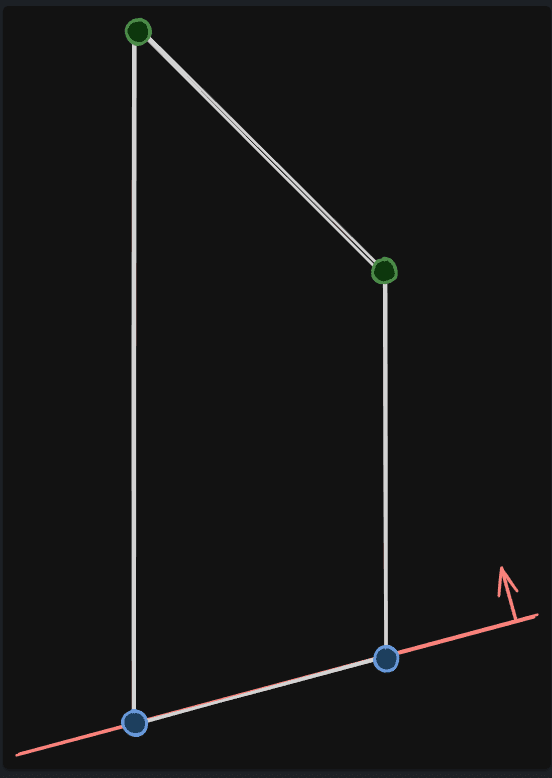
}폴리곤을 평면으로 자르고 전방의 폴리곤과 후방의 폴리곤으로 분리
SplitWithPlaneFast를 통해 폴리곤을 주어진 평면 기준의 앞쪽과 뒷쪽의 폴리곤으로 분류한다.
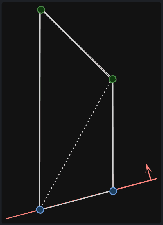
흰색 폴리곤은 빨간색 평면에 의해 Split되어 평면의 전방에 있는 녹색점 2개와 파란점 2개를 가지는 Front와 평면의 후방에 있는 빨간점 2개와 파란점 2개를 가지는 Back으로 분류 된다.
우선 각 정점들의 평면의 전방or후방 여부를 지정하기 위한 준비들을 한다.
int32 FPoly::SplitWithPlaneFast
(
    const FPlane&  Plane,
    FPoly*       FrontPoly,
    FPoly*       BackPoly
) const
{
    FMemMark MemMark( FMemStack::Get() );

    enum EPlaneClassification
    {
        V_FRONT=0,
        V_BACK=1
    };

    EPlaneClassification Status,PrevStatus;
    EPlaneClassification* VertStatus = new( FMemStack::Get() ) EPlaneClassification[ Vertices.Num() ];
    int32 Front = 0, Back = 0;

    EPlaneClassification* StatusPtr = &VertStatus[ 0 ];
그 후 평면과 각 정점과의 거리를 구해 전방or후방 위치를 결정한다.
for( int32 i = 0; i < Vertices.Num(); i++ )
{
    float Dist = Plane.PlaneDot( (FVector)Vertices[ i ] );
    if( Dist >= 0.f )
    {
        *StatusPtr++ = V_FRONT;
        if( Dist > +UE_THRESH_SPLIT_POLY_WITH_PLANE )
            Front=1;
    }
    else
    {
        *StatusPtr++ = V_BACK;
        if( Dist < -UE_THRESH_SPLIT_POLY_WITH_PLANE )
            Back=1;
    }
}
폴리곤 전체에 대해 전방에 있는지 후방에 있는지, 잘라야 하는지 혹은 평행하는지 여부를 검사한다.
ESplitType Result;
if( !Front )
{
    if( Back ) Result = SP_Back;
    else       Result = SP_Coplanar;
}
else if( !Back )
{
    Result = SP_Front;
}
잘라야 하는 경우 선분과 평면의 교차점을 구하는 방법으로 Interection지점을 구해 Front, Back 폴리곤 모두에게 추가해주고 기존 폴리곤을 구성하는 정점은 각각 Front와 Back에 분류하여 추가해준다.
if( FrontPoly )
{
    const FVector3f *V = Vertices.GetData();
    const FVector3f *W = V + Vertices.Num()-1;
    FVector3f *V1      = FrontPoly->Vertices.GetData();
    FVector3f *V2      = BackPoly ->Vertices.GetData();
    StatusPtr          = &VertStatus[ 0 ];
    PrevStatus         = VertStatus [ Vertices.Num() - 1 ];

    for ( int32 i = 0; i < Vertices.Num(); i++ )
    {
        Status = *StatusPtr++;
        if( Status != PrevStatus )
        {
            const FVector3f& Intersection = FMath::LinePlaneIntersection( *W, *V, (FPlane4f)Plane );

            new( FrontPoly->Vertices ) FVector3f( Intersection );
            new( BackPoly ->Vertices ) FVector3f( Intersection );

            if( PrevStatus == V_FRONT )
            {
                new( BackPoly->Vertices ) FVector3f( *V );
            }
            else
            {
                new( FrontPoly->Vertices ) FVector3f( *V );
            }
        }
        else if( Status==V_FRONT )
        {
            new( FrontPoly->Vertices ) FVector3f( *V );
        }
        else
        {
            new( BackPoly->Vertices ) FVector3f( *V );
        }

        PrevStatus = Status;
        W          = V++;
    }
    FrontPoly->Base      = Base;
    FrontPoly->Normal     Normal;
    FrontPoly->PolyFlags = PolyFlags;

    BackPoly->Base       = Base;
    BackPoly->Normal     = Normal;
    BackPoly->PolyFlags  = PolyFlags;
}
Result = SP_Split;
이 코드를 도식화하면 다음과 같다. 폴리곤을 구성하는 정점 4개는 [ 0, 1, 2, 3 ]의 순서대로 담겨 있다.
처음에 V와 W는 각각 첫번째와 마지막 정점을 가리키므로 왼쪽과 같은 모습이 된다.
마지막 W = V++;를 통해 W는 V가 되고 V는 다음 인덱로 증가되므로 중앙의 모습이 된다.
이런식으로 4개의 정점들로 이루어지는 라인을 평면과 Intersect검출을 하여 교차점을 찾아내는 것이다.
최종적으로 앞면에 있는 폴리곤을 사용하므로 최종적으로는 아래와 같이 구성된 폴리곤을 얻게 된다.
정점 구성이 완료된 폴리곤의 인덱스 설정
한번 정리된 폴리곤의 정점들을 순회하면서 기존 충돌체를 구성하는 정점들과 비교하여 동일한 위치라고 판단되는 정점이 있으면 해당 정점을 사용한다. 따라서 위와 같이 평면에 의해 잘려 새롭게 생성된 정점( 파란색 ) 이 아닌 기존 정점( 녹색 )은 그대로 기존 정점을 사용하게 된다. 그리고 새로운 정점을 추가( AddVertexIfNotPresent )할 때도 기존 정점과 동일한 위치인지 판단 후 추가를 하게 된다.
그리고 정점의 필터링이 끝나면 이 정점에 대한 인덱스를 지정하여 Remap에 보관한다.
if ( Polygon.Vertices.Num() > 0 )
{
    TArray< int32 > Remap;
    Remap.AddUninitialized( Polygon.Vertices.Num() );

    TotalPolyArea += Polygon.Area();

    for ( int32 j = 0; j < Polygon.Vertices.Num() ; j++ )
    {
        int32 NearestVert = INDEX_NONE;
        float NearestDistSqr = UE_BIG_NUMBER;

        for ( int32 k = 0; k < SnapVerts.Num(); k++ )
        {
            const float DistSquared = ((FVector)Polygon.Vertices[ j ] - (FVector)SnapVerts[ k ]).SizeSquared();

            if ( DistSquared < NearestDistSqr )
            {
                NearestVert = k;
                NearestDistSqr = DistSquared;
            }
        }

        if ( NearestVert != INDEX_NONE && NearestDistSqr < InSnapDistance)
        {
            const FVector localVert = SnapVerts[ NearestVert ];
            Remap[ j ] = AddVertexIfNotPresent( VertexData, localVert );
        }
        else
        {
            const FVector localVert = (FVector)Polygon.Vertices[ j ];
            Remap[ j ] = AddVertexIfNotPresent( VertexData, localVert );
        }
}
정점들의 정리 및 정점들의 인덱스 지정이 모두 끝나면 삼각형 형태의 Face를 구성하도록 인덱스 버퍼를 설정한다.
    const int32 NumTriangles = Polygon.Vertices.Num() - 2;
    const int32 BaseIndex = Remap[ 0 ];
    for ( int32 Index = 0; Index < NumTriangles; ++Index )
    {
        IndexData.Add( BaseIndex );
        IndexData.Add( Remap[ Index + 1 ] );
        IndexData.Add( Remap[ Index + 2 ] );
    }
}
위 과정이 끝난 하나의 평면은 다음과 같은 모습이 된다.
충돌체가 평면에 의해 성공적으로 분리되었는지 검증
// 폴리곤이 차지하는 바운더리가 너무 작은 경우 실패
if ( TotalPolyArea < 0.001f )
{
   UE_LOG( LogPhysics, Log,  TEXT( "Total Polygon Area invalid: %f" ), TotalPolyArea );
   return false;
}

// 정점 갯수가 평면을 구성하지 못하는 경우 실패 ( 적어도 4개는 되어야 함 )
if ( VertexData.Num() < 4 )
{
    return false;
}

FVector Dir2, Dir1;

Dir1 = VertexData[ 1 ] - VertexData[ 0 ];
Dir1.Normalize();

// 한 점에서 나머지 점들에 대한 방향을 비교하여 동일한 방향을 가지는 점이 있는지 체크한다.
// 만약 동일한 방향을 가지는 점이 있는 경우 이는 정점들의 정리가 제대로 안된 것이라고 할 수 있다.
for ( int32 i = 2; i < VertexData.Num() && !bFound; i++ )
{
    Dir2 = VertexData[ i ] - VertexData[ 0 ];
    Dir2.Normalize();


    if ( ( Dir1 | Dir2 ) < ( 1.f - LOCAL_EPS ) )
    {
        bFound = true;
    }
}

if ( !bFound )
{
    return false;
}

FVector Normal = Dir1 ^ Dir2;
Normal.Normalize();

const FPlane Plane( VertexData[ 0 ], Normal );

// 모든 정점이 동일한 노말 방향을 가지고 있는지 검증한다.
bFound = false;
for ( int32 i = 2; i < VertexData.Num() ; i++ )
{
    if ( FMath::Abs( Plane.PlaneDot( VertexData[ i ] ) ) > LOCAL_EPS )
    {
        bFound = true;
        break;
    }
}

if ( !bFound )
{
    return false;
}

UpdateElemBox();

return true;
검증이 모두 성공적으로 끝나면 충돌체 바운더리를 갱신한다.
잘린 충돌체를 메쉬 컴포넌트의 충돌체로 설정
SliceConvexElem에서 모든 과정이 성공적으로 끝나면 SlicedConvexVerts에 새롭게 잘린 충돌체 정점들이 담겨있게 된다.
이 정점들은 SlicedCollision에 모와두고 모든 충돌체에 대한 처리가 끝나면 SetCollisionConvexMeshes를 통해 메쉬의 충돌체로 설정되게 된다.
이때 잘려나가는 메쉬에 대한 설정도 필요하면 자르는 평면만 뒤집어서 같은 처리를 반복한다.
해당 코드가 바로 SliceConvexElem( BaseConvex, SlicePlane.Flip(), OtherSlicedConvexVerts );이다.
        TArray< FVector > SlicedConvexVerts;
        SliceConvexElem( BaseConvex, SlicePlane, SlicedConvexVerts );

        if ( SlicedConvexVerts.Num() >= 4 )
        {
            SlicedCollision.Add( SlicedConvexVerts );
        }

        if ( bCreateOtherHalf )
        {
            TArray< FVector > OtherSlicedConvexVerts;
            SliceConvexElem( BaseConvex, SlicePlane.Flip(), OtherSlicedConvexVerts );

            if ( OtherSlicedConvexVerts.Num() >= 4 )
            {
                OtherSlicedCollision.Add( OtherSlicedConvexVerts );
            }
        }
    }
}

InProcMesh->SetCollisionConvexMeshes( SlicedCollision );
잘려나간 메쉬의 보존
잘려나간 메쉬부분을 보존한다면 이를 위해 새로운 UProceduralMeshComponent를 생성하고 캐슁중인 메쉬섹션, 머티리얼, 충돌체 정보등을 해당 컴포넌트에 설정해준다.
if ( bCreateOtherHalf )
{
    OutOtherHalfProcMesh = NewObject< UProceduralMeshComponent >( InProcMesh->GetOuter() );
    OutOtherHalfProcMesh->SetWorldTransform( InProcMesh->GetComponentTransform() );

    for ( int32 SectionIndex = 0; SectionIndex < OtherSections.Num(); SectionIndex++ )
    {
       OutOtherHalfProcMesh->SetProcMeshSection( SectionIndex, OtherSections[ SectionIndex ] );
       OutOtherHalfProcMesh->SetMaterial( SectionIndex, OtherMaterials[ SectionIndex ] );
    }

    OutOtherHalfProcMesh->SetCollisionProfileName( InProcMesh->GetCollisionProfileName() );
    OutOtherHalfProcMesh->SetCollisionEnabled( InProcMesh->GetCollisionEnabled() );
    OutOtherHalfProcMesh->bUseComplexAsSimpleCollision = InProcMesh->bUseComplexAsSimpleCollision;
    OutOtherHalfProcMesh->SetCollisionConvexMeshes( OtherSlicedCollision );
    OutOtherHalfProcMesh->RegisterComponent();
}


댓글을 남겨주세요
Want to join the discussion?Feel free to contribute!