충돌체 분리하기
메쉬가 가지고 있는 충돌체또한 분리가 필요하다. 분리하는 충돌체는 메쉬에 설정된 UBodySetup이 기준이다.
충돌체의 바운더리를 평면이 관통하는지 검사
먼저, 메쉬의 바운더리를 평면이 관통하는지 검사했던것 처럼 충돌체의 바운더리 역시 평면이 관통하는지 검사를 한다.
TArray< TArray< FVector > > SlicedCollision;
TArray< TArray< FVector > > OtherSlicedCollision;

UBodySetup* ProcMeshBodySetup = InProcMesh->GetBodySetup();

for ( int32 ConvexIndex = 0; ConvexIndex < ProcMeshBodySetup->AggGeom.ConvexElems.Num(); ConvexIndex++ )
{
    FKConvexElem& BaseConvex = ProcMeshBodySetup->AggGeom.ConvexElems[ ConvexIndex ];

    int32 BoxCompare = BoxPlaneCompare( BaseConvex.ElemBox, SlicePlane );

    if ( BoxCompare == -1 )
    {
        if ( bCreateOtherHalf )
        {
            OtherSlicedCollision.Add( BaseConvex.VertexData );
        }
    }
    else if ( BoxCompare == 1 )
    {
        SlicedCollision.Add( BaseConvex.VertexData );
    }
충돌체의 바운더리를 평면이 관통할 때 슬라이스 처리
TArray< FVector > SlicedConvexVerts;
SliceConvexElem( BaseConvex, SlicePlane, SlicedConvexVerts );
충돌체를 자르는 함수 SliceConvexElem의 내용은 다음과 같다.
void SliceConvexElem( const FKConvexElem& InConvex, const FPlane& SlicePlane, TArray< FVector >& OutConvexVerts )
{
    TArray< FPlane > ConvexPlanes;
    InConvex.GetPlanes( ConvexPlanes );

    if ( ConvexPlanes.Num() >= 4 )
    {
       ConvexPlanes.Add( SlicePlane.Flip() );

       FKConvexElem SlicedElem;
       bool bSuccess = SlicedElem.HullFromPlanes( ConvexPlanes, InConvex.VertexData );
       if ( bSuccess )
       {
          OutConvexVerts = SlicedElem.VertexData;
       }
    }
}
충돌체를 구성하는 평면들의 수집
InConvex.GetPlanes( ConvexPlanes )를 보면 우선적으로 충돌체를 구성하는 평면들을 가져온다.GetPlanes함수의 내용은 다음과 같다.
void FKConvexElem::GetPlanes( TArray< FPlane >& Planes ) const
{
    using FChaosPlane = Chaos::TPlaneConcrete< Chaos::FReal, 3 >;

    if ( Chaos::FConvex* RawConvex = ChaosConvex.GetReference() )
    {
        const int32 NumPlanes = RawConvex->NumPlanes();

        for( int32 i = 0; i < NumPlanes; ++i )
        {
            const FChaosPlane& Plane = RawConvex->GetPlane( i );

            Planes.Add( { Plane.X(), Plane.Normal() } );
        }
    }
}
충돌체를 구성하는 평면들을 자르기
우선 충돌체를 구성하는 평면이 4개 이상이여야 완전히 닫힌 상태의 온전한 충돌체로 판단하여 자르는 것을 시도한다. 이 충돌체를 자르는 함수가 HullFromPlanes이다.
평면을 표현하는 폴리곤 준비
가장 먼저 할것은 충돌체를 구성하는 평면을 폴리곤 형태로 바꾸는 것이다. 이를 위해 평면의 중심점 Base에서 엔진에서 지원하는 최대 월드 크기로 평면이 구성되는 폴리곤을 구성한다.
bool FKConvexElem::HullFromPlanes( const TArray< FPlane >& InPlanes, const TArray< FVector >& SnapVerts, float InSnapDistance )
{
    Reset();

    float TotalPolyArea = 0;

    for ( int32 i = 0; i < InPlanes.Num(); i++ )
    {
       FPoly Polygon;
       Polygon.Normal = (FVector3f)InPlanes[ i ];

       FVector3f AxisX, AxisY;
       Polygon.Normal.FindBestAxisVectors( AxisX, AxisY );

       const FVector3f Base = FVector3f( InPlanes[ i ] * InPlanes[ i ].W );

       new( Polygon.Vertices ) FVector3f( Base + AxisX * UE_OLD_HALF_WORLD_MAX + AxisY * UE_OLD_HALF_WORLD_MAX );
       new( Polygon.Vertices ) FVector3f( Base - AxisX * UE_OLD_HALF_WORLD_MAX + AxisY * UE_OLD_HALF_WORLD_MAX );
       new( Polygon.Vertices ) FVector3f( Base - AxisX * UE_OLD_HALF_WORLD_MAX - AxisY * UE_OLD_HALF_WORLD_MAX );
       new( Polygon.Vertices ) FVector3f( Base + AxisX * UE_OLD_HALF_WORLD_MAX - AxisY * UE_OLD_HALF_WORLD_MAX );
폴리곤을 충돌체를 구성하는 다른 평면들로 자름
폴리곤을 충돌체를 구성하는 다른 평면들로 자름으로서 다른 평면의 전방에 있는 정점들로 구성된 폴리곤의 정점을 다시 조정하게 된다.
for ( int32 j = 0; j < InPlanes.Num(); j++ )
{
    if ( i != j )
    {
        if ( !Polygon.Split( -FVector3f( InPlanes[ j ] ), FVector3f( InPlanes[ j ] * InPlanes[ j ].W ) ) )
        {
            Polygon.Vertices.Empty();
            break;
        }
    }
}
Polygon.Split의 결과가 0인 경우는 이 폴리곤을 구성하는 모든 정점이 자르는 평면의 뒷쪽에 있어 유효한 충돌체를 구성하는 폴리곤이 아니게 되므로 이 폴리곤을 구성하는 정점은 모두 제거한다.
Split함수의 내용은 다음과 같다.
int32 FPoly::Split( const FVector3f &InNormal, const FVector3f &InBase )
{
    FPoly Front, Back;

    Front.Init();
    Back .Init();

    switch( SplitWithPlaneFast( FPlane( (FVector)InBase, (FVector)InNormal ), &Front, &Back ) )
    {
       case SP_Back:
          return 0;
       case SP_Split:
          *this = Front;
          return Vertices.Num();
       default:
          return Vertices.Num();
    }
}
폴리곤을 평면으로 자르고 전방의 폴리곤과 후방의 폴리곤으로 분리
SplitWithPlaneFast를 통해 폴리곤을 주어진 평면 기준의 앞쪽과 뒷쪽의 폴리곤으로 분류한다.
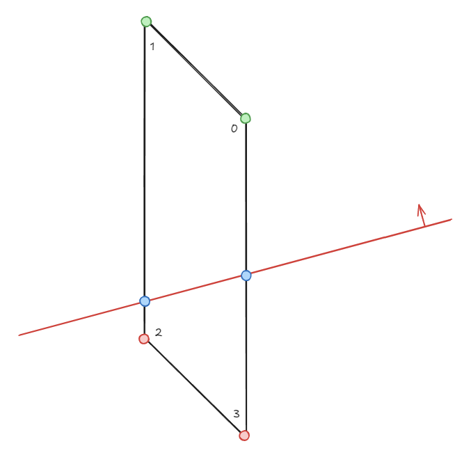
흰색 폴리곤은 빨간색 평면에 의해 Split되어 평면의 전방에 있는 녹색점 2개와 파란점 2개를 가지는 Front와 평면의 후방에 있는 빨간점 2개와 파란점 2개를 가지는 Back으로 분류 된다.
우선 각 정점들의 평면의 전방or후방 여부를 지정하기 위한 준비들을 한다.
int32 FPoly::SplitWithPlaneFast
(
    const FPlane&  Plane,
    FPoly*       FrontPoly,
    FPoly*       BackPoly
) const
{
    FMemMark MemMark( FMemStack::Get() );

    enum EPlaneClassification
    {
        V_FRONT=0,
        V_BACK=1
    };

    EPlaneClassification Status,PrevStatus;
    EPlaneClassification* VertStatus = new( FMemStack::Get() ) EPlaneClassification[ Vertices.Num() ];
    int32 Front = 0, Back = 0;

    EPlaneClassification* StatusPtr = &VertStatus[ 0 ];
그 후 평면과 각 정점과의 거리를 구해 전방or후방 위치를 결정한다.
for( int32 i = 0; i < Vertices.Num(); i++ )
{
    float Dist = Plane.PlaneDot( (FVector)Vertices[ i ] );
    if( Dist >= 0.f )
    {
        *StatusPtr++ = V_FRONT;
        if( Dist > +UE_THRESH_SPLIT_POLY_WITH_PLANE )
            Front=1;
    }
    else
    {
        *StatusPtr++ = V_BACK;
        if( Dist < -UE_THRESH_SPLIT_POLY_WITH_PLANE )
            Back=1;
    }
}
폴리곤 전체에 대해 전방에 있는지 후방에 있는지, 잘라야 하는지 혹은 평행하는지 여부를 검사한다.
ESplitType Result;
if( !Front )
{
    if( Back ) Result = SP_Back;
    else       Result = SP_Coplanar;
}
else if( !Back )
{
    Result = SP_Front;
}
잘라야 하는 경우 선분과 평면의 교차점을 구하는 방법으로 Interection지점을 구해 Front, Back 폴리곤 모두에게 추가해주고 기존 폴리곤을 구성하는 정점은 각각 Front와 Back에 분류하여 추가해준다.
if( FrontPoly )
{
    const FVector3f *V = Vertices.GetData();
    const FVector3f *W = V + Vertices.Num()-1;
    FVector3f *V1      = FrontPoly->Vertices.GetData();
    FVector3f *V2      = BackPoly ->Vertices.GetData();
    StatusPtr          = &VertStatus[ 0 ];
    PrevStatus         = VertStatus [ Vertices.Num() - 1 ];

    for ( int32 i = 0; i < Vertices.Num(); i++ )
    {
        Status = *StatusPtr++;
        if( Status != PrevStatus )
        {
            const FVector3f& Intersection = FMath::LinePlaneIntersection( *W, *V, (FPlane4f)Plane );

            new( FrontPoly->Vertices ) FVector3f( Intersection );
            new( BackPoly ->Vertices ) FVector3f( Intersection );

            if( PrevStatus == V_FRONT )
            {
                new( BackPoly->Vertices ) FVector3f( *V );
            }
            else
            {
                new( FrontPoly->Vertices ) FVector3f( *V );
            }
        }
        else if( Status==V_FRONT )
        {
            new( FrontPoly->Vertices ) FVector3f( *V );
        }
        else
        {
            new( BackPoly->Vertices ) FVector3f( *V );
        }

        PrevStatus = Status;
        W          = V++;
    }
    FrontPoly->Base      = Base;
    FrontPoly->Normal     Normal;
    FrontPoly->PolyFlags = PolyFlags;

    BackPoly->Base       = Base;
    BackPoly->Normal     = Normal;
    BackPoly->PolyFlags  = PolyFlags;
}
Result = SP_Split;
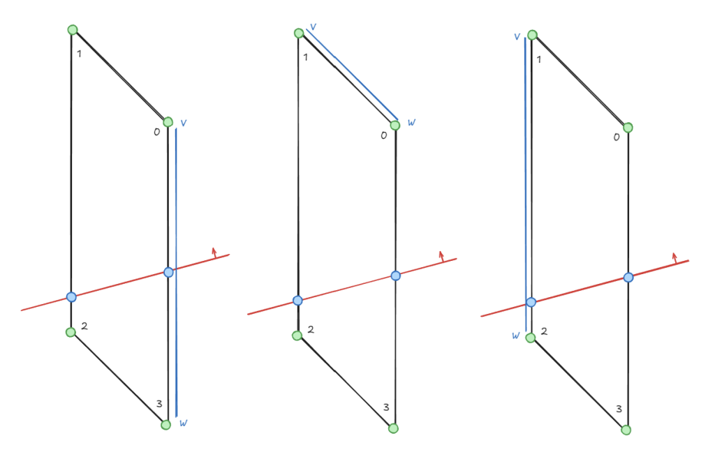
이 코드를 도식화하면 다음과 같다. 폴리곤을 구성하는 정점 4개는 [ 0, 1, 2, 3 ]의 순서대로 담겨 있다.
처음에 V와 W는 각각 첫번째와 마지막 정점을 가리키므로 왼쪽과 같은 모습이 된다.
마지막 W = V++;를 통해 W는 V가 되고 V는 다음 인덱로 증가되므로 중앙의 모습이 된다.
이런식으로 4개의 정점들로 이루어지는 라인을 평면과 Intersect검출을 하여 교차점을 찾아내는 것이다.
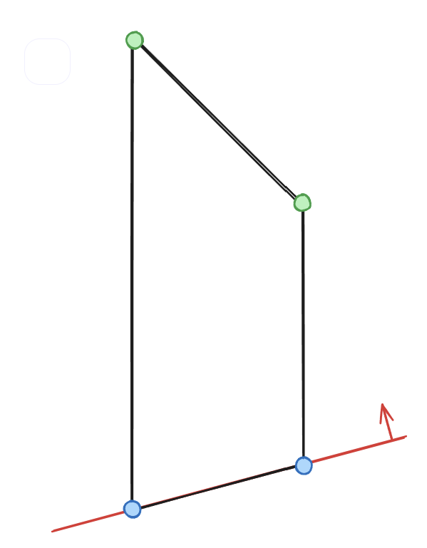
최종적으로 앞면에 있는 폴리곤을 사용하므로 최종적으로는 아래와 같이 구성된 폴리곤을 얻게 된다.
정점 구성이 완료된 폴리곤의 인덱스 설정
한번 정리된 폴리곤의 정점들을 순회하면서 기존 충돌체를 구성하는 정점들과 비교하여 동일한 위치라고 판단되는 정점이 있으면 해당 정점을 사용한다. 따라서 위와 같이 평면에 의해 잘려 새롭게 생성된 정점( 파란색 ) 이 아닌 기존 정점( 녹색 )은 그대로 기존 정점을 사용하게 된다. 그리고 새로운 정점을 추가( AddVertexIfNotPresent )할 때도 기존 정점과 동일한 위치인지 판단 후 추가를 하게 된다.
그리고 정점의 필터링이 끝나면 이 정점에 대한 인덱스를 지정하여 Remap에 보관한다.
if ( Polygon.Vertices.Num() > 0 )
{
    TArray< int32 > Remap;
    Remap.AddUninitialized( Polygon.Vertices.Num() );

    TotalPolyArea += Polygon.Area();

    for ( int32 j = 0; j < Polygon.Vertices.Num() ; j++ )
    {
        int32 NearestVert = INDEX_NONE;
        float NearestDistSqr = UE_BIG_NUMBER;

        for ( int32 k = 0; k < SnapVerts.Num(); k++ )
        {
            const float DistSquared = ((FVector)Polygon.Vertices[ j ] - (FVector)SnapVerts[ k ]).SizeSquared();

            if ( DistSquared < NearestDistSqr )
            {
                NearestVert = k;
                NearestDistSqr = DistSquared;
            }
        }

        if ( NearestVert != INDEX_NONE && NearestDistSqr < InSnapDistance)
        {
            const FVector localVert = SnapVerts[ NearestVert ];
            Remap[ j ] = AddVertexIfNotPresent( VertexData, localVert );
        }
        else
        {
            const FVector localVert = (FVector)Polygon.Vertices[ j ];
            Remap[ j ] = AddVertexIfNotPresent( VertexData, localVert );
        }
}
정점들의 정리 및 정점들의 인덱스 지정이 모두 끝나면 삼각형 형태의 Face를 구성하도록 인덱스 버퍼를 설정한다.
    const int32 NumTriangles = Polygon.Vertices.Num() - 2;
    const int32 BaseIndex = Remap[ 0 ];
    for ( int32 Index = 0; Index < NumTriangles; ++Index )
    {
        IndexData.Add( BaseIndex );
        IndexData.Add( Remap[ Index + 1 ] );
        IndexData.Add( Remap[ Index + 2 ] );
    }
}
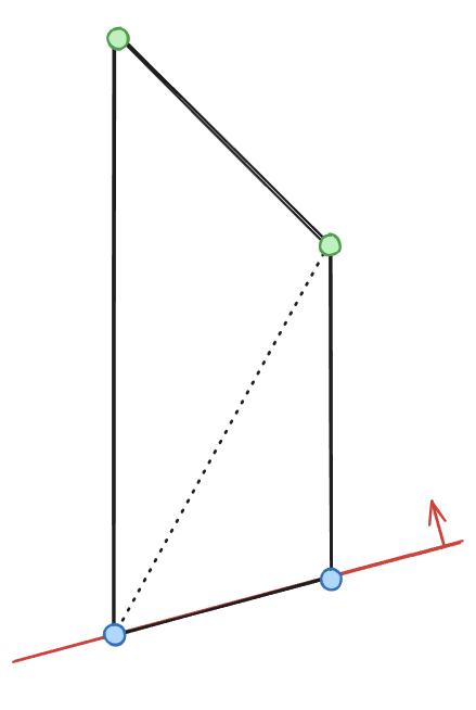
위 과정이 끝난 하나의 평면은 다음과 같은 모습이 된다.
충돌체가 평면에 의해 성공적으로 분리되었는지 검증
// 폴리곤이 차지하는 바운더리가 너무 작은 경우 실패
if ( TotalPolyArea < 0.001f )
{
   UE_LOG( LogPhysics, Log,  TEXT( "Total Polygon Area invalid: %f" ), TotalPolyArea );
   return false;
}

// 정점 갯수가 평면을 구성하지 못하는 경우 실패 ( 적어도 4개는 되어야 함 )
if ( VertexData.Num() < 4 )
{
    return false;
}

FVector Dir2, Dir1;

Dir1 = VertexData[ 1 ] - VertexData[ 0 ];
Dir1.Normalize();

// 한 점에서 나머지 점들에 대한 방향을 비교하여 동일한 방향을 가지는 점이 있는지 체크한다.
// 만약 동일한 방향을 가지는 점이 있는 경우 이는 정점들의 정리가 제대로 안된 것이라고 할 수 있다.
for ( int32 i = 2; i < VertexData.Num() && !bFound; i++ )
{
    Dir2 = VertexData[ i ] - VertexData[ 0 ];
    Dir2.Normalize();


    if ( ( Dir1 | Dir2 ) < ( 1.f - LOCAL_EPS ) )
    {
        bFound = true;
    }
}

if ( !bFound )
{
    return false;
}

FVector Normal = Dir1 ^ Dir2;
Normal.Normalize();

const FPlane Plane( VertexData[ 0 ], Normal );

// 모든 정점이 동일한 노말 방향을 가지고 있는지 검증한다.
bFound = false;
for ( int32 i = 2; i < VertexData.Num() ; i++ )
{
    if ( FMath::Abs( Plane.PlaneDot( VertexData[ i ] ) ) > LOCAL_EPS )
    {
        bFound = true;
        break;
    }
}

if ( !bFound )
{
    return false;
}

UpdateElemBox();

return true;
검증이 모두 성공적으로 끝나면 충돌체 바운더리를 갱신한다.
잘린 충돌체를 메쉬 컴포넌트의 충돌체로 설정
SliceConvexElem에서 모든 과정이 성공적으로 끝나면 SlicedConvexVerts에 새롭게 잘린 충돌체 정점들이 담겨있게 된다.
이 정점들은 SlicedCollision에 모와두고 모든 충돌체에 대한 처리가 끝나면 SetCollisionConvexMeshes를 통해 메쉬의 충돌체로 설정되게 된다.
이때 잘려나가는 메쉬에 대한 설정도 필요하면 자르는 평면만 뒤집어서 같은 처리를 반복한다.
해당 코드가 바로 SliceConvexElem( BaseConvex, SlicePlane.Flip(), OtherSlicedConvexVerts );이다.
        TArray< FVector > SlicedConvexVerts;
        SliceConvexElem( BaseConvex, SlicePlane, SlicedConvexVerts );

        if ( SlicedConvexVerts.Num() >= 4 )
        {
            SlicedCollision.Add( SlicedConvexVerts );
        }

        if ( bCreateOtherHalf )
        {
            TArray< FVector > OtherSlicedConvexVerts;
            SliceConvexElem( BaseConvex, SlicePlane.Flip(), OtherSlicedConvexVerts );

            if ( OtherSlicedConvexVerts.Num() >= 4 )
            {
                OtherSlicedCollision.Add( OtherSlicedConvexVerts );
            }
        }
    }
}

InProcMesh->SetCollisionConvexMeshes( SlicedCollision );
잘려나간 메쉬의 보존
잘려나간 메쉬부분을 보존한다면 이를 위해 새로운 UProceduralMeshComponent를 생성하고 캐슁중인 메쉬섹션, 머티리얼, 충돌체 정보등을 해당 컴포넌트에 설정해준다.
if ( bCreateOtherHalf )
{
    OutOtherHalfProcMesh = NewObject< UProceduralMeshComponent >( InProcMesh->GetOuter() );
    OutOtherHalfProcMesh->SetWorldTransform( InProcMesh->GetComponentTransform() );

    for ( int32 SectionIndex = 0; SectionIndex < OtherSections.Num(); SectionIndex++ )
    {
       OutOtherHalfProcMesh->SetProcMeshSection( SectionIndex, OtherSections[ SectionIndex ] );
       OutOtherHalfProcMesh->SetMaterial( SectionIndex, OtherMaterials[ SectionIndex ] );
    }

    OutOtherHalfProcMesh->SetCollisionProfileName( InProcMesh->GetCollisionProfileName() );
    OutOtherHalfProcMesh->SetCollisionEnabled( InProcMesh->GetCollisionEnabled() );
    OutOtherHalfProcMesh->bUseComplexAsSimpleCollision = InProcMesh->bUseComplexAsSimpleCollision;
    OutOtherHalfProcMesh->SetCollisionConvexMeshes( OtherSlicedCollision );
    OutOtherHalfProcMesh->RegisterComponent();
}
이전글 : UKismetProceduralMeshLibrary의 SliceProceduralMesh 함수 분석 – 1